From words and drawings into 3D data, automatically.
AI operates Fusion 360 to create 3D data for parts and enclosures. The data goes to our own machining centers and SLS 3D printer, straight into prototypes.
AI × FUSION 360Builds the 3D data automatically. CAM → Machining & printing
Three kinds of input, one set of 3D data.
R&D that LMR pursues together with its own prototyping department.
01 / CONCEPTAbout this system
AI-driven 3D design Design to machining, in one flow.
On the shop floor, turning drawings into 3D models and writing machining programs by hand are still common. This system aims to have AI create Fusion 360 3D data automatically from written requirements or 2D drawings, and carry it through to machining preparation.
Input
Written requirements (size, mounting, the device inside and so on), 2D drawings (DXF) and 3D scans of real objects.
Output
3D data you can open and edit in Fusion 360 (STEP and more), ready for people to check, finish and change.
Connected to
From the 3D data, CAM produces the machining program for our own machining centers (3- and 5-axis). Resin parts are made on the SLS 3D printer.
Fusion 3603D CADCAM
AI-DESIGNED PARTDesign example
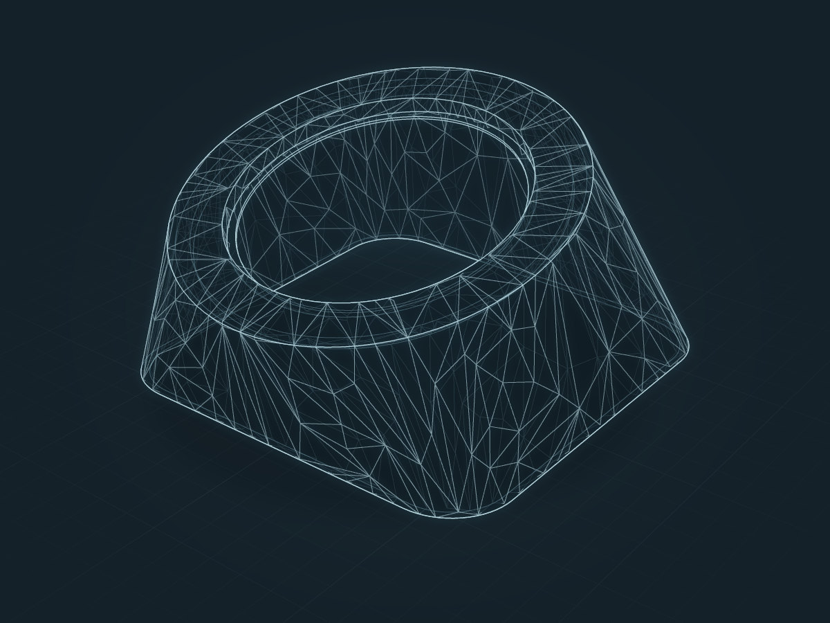
A sensor enclosure designed by AI operating Fusion 360. The shape was fitted to the 3D data of the device inside and designed for SLS 3D printing. The image shows that 3D data as a see-through wireframe.
KEY IDEA
Not pictures, but 3D data you can machine.
02 / TWO ROUTESTwo routes
Two routes Design from words. Build solids from drawings.
Depending on the goal, 3D data is created in one of two ways.
ROUTE 01
Design from words
Describe the size, how it mounts and what goes inside, and AI operates Fusion 360 directly, combining sketches, extrusions, lofts and shells to shape enclosures and jigs. Dimensions can be fitted to the 3D data of the device inside.
ROUTE 02
From drawings to solids
It reads the lines, dimensions and thread callouts of a 2D drawing (DXF) and builds the 3D model with a method suited to the type of part: shafts, bearings, enclosures and more. Parts with nothing but a drawing become usable 3D data.
03 / HOW IT WORKSRead, assemble, check
Five stages From clues to data you can machine.
01Read
Dimensions, holes, threads and shape clues are extracted from requirements, drawings and scan data.
02Assemble
AI assembles the steps that make the shape (sketches, extrusions, holes and so on) as a program.
03Make the shape
The assembled steps run in 3D CAD such as Fusion 360 to create the solid.
04Check
Dimensions and shape are checked against the drawing and the requirements. In development, we improve the system by measuring shape agreement on pairs of real part drawings and 3D models.
05Connect to machining
From the 3D data, CAM produces the machining program, and the machining centers or the SLS 3D printer make the prototype. We are also researching CAM automation.
04 / WHY IT MATTERSWhat it is good for
How it helps Less design work, faster prototypes.
01
Less drafting work
AI takes on turning drawings into 3D and drafting enclosures and jigs, so people can spend their time checking and finishing.
02
Faster prototyping
Because design, machining and printing are connected in-house, the loop of checking, fixing and making again gets shorter.
03
Put drawings to work
Parts that survive only as 2D or paper drawings can become 3D data for remaking and improvement.
04
Support the shop floor
Even where machining programs are still written by hand, it becomes easier to build a flow from 3D data to machining.
Where we see it helping
Designing prototype parts, jigs and device enclosures
Turning existing parts that only have 2D drawings into 3D data
Remaking replacement parts with 3D scanning
Bringing molds and machining parts in-house
These are envisaged uses, not a record of deployments.
05 / STATUSWhere we are now
Where the R&D stands Tested on our own shop floor.
This system is developed together with LMR’s prototyping department. We improve it by actually making the designed data on our own machining centers and SLS 3D printer.
Working now
AI can operate Fusion 360 to design enclosures and other parts. Drawing-to-3D conversion is being made more accurate by measuring shape agreement on evaluation parts.
In progress
Making drawing-to-3D conversion more accurate, and automating through to CAM (machining programs).
Equipment
Machining centers (3- and 5-axis), an SLS 3D printer and a 3D scanner.
NOTE
Autodesk and Fusion 360 are registered trademarks or trademarks of Autodesk, Inc. in the USA and other countries.
The design example illustrates how the system works.